AUTOMATIC PID-TUNER (APT-1)
1. Problem to be resolved by the tuner
The changes of parameters of technological process generate a need of change (tuning) of PID-controller parameters (proportional gain  , integral
  and derivative
  gains) to keep the quality of technological process control.
The controller parameters are tuned by human-operator or by making use of algorithm of self-tuning of PID-controlled. If the plant works under intensive external disturbances then the actions of operator and the known facilities for controller self-tuning are ineffective.
Automatic PID-tuner APT-1 makes the tuning of PID-controller when the parameters of technological process changed and the intensive external disturbance are applied to the plant.
2. Description
2.1. The scheme of the tuner connection
The tuner is implemented in the industrial controller. The scheme of connection is shown on fig.1
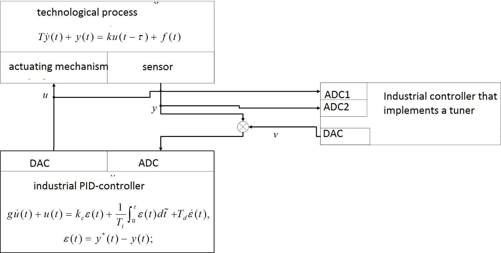
Fig. 1. The scheme of the tuner connection
The signals from input  and output
 of controller are applied to the tuner inputs. The tuner output, referred as the test signal
  , and the reference signal
  applied to the controller input.
The test signal is tuned so that the deviation from reference signal is the specified small part of deviation that is caused by external disturbance.
applied to the controller input.
The test signal is tuned so that the deviation from reference signal is the specified small part of deviation that is caused by external disturbance.
2.2. Regimes of Operation
The first regime (identification)
The results of this regime of tuner operation are the coefficients of the first order plant with time delay:
 — gain,
 — time response,
 — delay. The human-operator uses these values for calculation of PID-controller parameters on the base of recommendation for concrete technological process.
The second regime (self-tuning)
The automatic tuner calculates the PIC-controller parameters making use of identified parameters of the plant and gives the controller parameters to the human-operator. The automatic tuner takes into account the recommendation for concrete technological process during calculation the controller parameters
,
and
,
Then the human-operator set s these parameters for controller that control this technological process который вводит их в контроллер, управляющий технологическим процессом. The another way of setting parameters
,
and
состоит
is the using of SCADA.
The third regime
differs from the second regime by the fact that the tuner calculates PID-controller parameters настройщик синтезирует ПИД-регулятор и находит числа,
и
,
by making use of specified synthesis procedure. The PID-controller is designed on the base of specified accuracy and quality requirements (rapidity of action, maximum overshoot, margins ) 3. The results of investigations of APT-1
The tuner is implemented in the industrial controller WinPAC-8441. .
We tested the tuner with use of the experimental setup that imitates semi-industrial environment.
This experimental setup includes two PLC controllers OWEN-150 and industrial controller WinPac-8441. The controllers OWEN imitates the technological process. The first PLC implements the plant with the facilities of periodic change of plant parameters. The second PLC implements PID-controller that controls the plant. The tuner is connected with technological process via the electrical signals only. The scheme of the experimental setup is shown on the fig.2
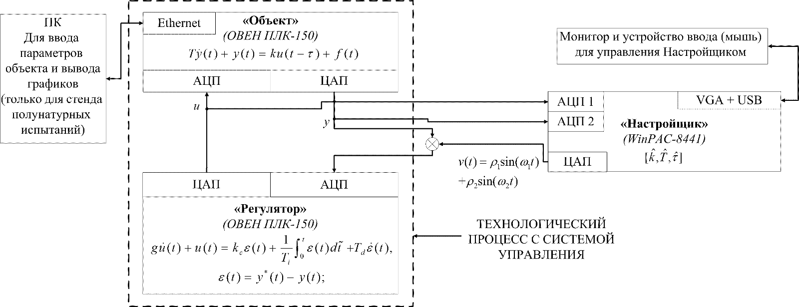
Fig. 2. The scheme of the experimental setup
The PID-controller is the standard functional block supplied with the development environment.
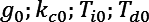
On the first regime of plant operation, the plant has the following parameters:

The external disturbance doesn’t change during the experiment. The disturbance is
 .
The reference signal is the constant
.
The reference signal is the constant  .
.
The controller coefficients were calculated for specified plant parameters
 .
.
Then the plant parameters changed. The values of new parameters are:
 The tuner identified plant parameters. The estimations of plant parameters on the output of the tuner were
  The test signal was:

The new controller coefficients were calculated by making use of the estimation of the plant coefficients
 .
.
The output of the plant in the start regime is shown on the fig.3 In this regime the plant coefficients are  ,
and controller coefficients that tuned for this plant
,
and controller coefficients that tuned for this plant
 .
.
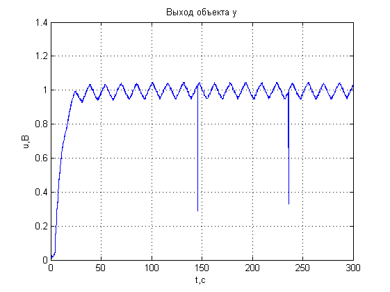
Fig. 3.The plant in the start regime, The controller tuned right
The output of the plant after the operation regime changed is shown on the fig.4 The coefficients of the plant
 ,
The controller coefficients did not change
.
,
The controller coefficients did not change
.
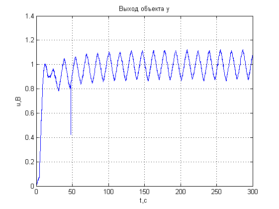
Fig. 4. The plant in the first regime, the controller in the zero regime
The output of the plant during the tuner operation is shown on the fig. 5
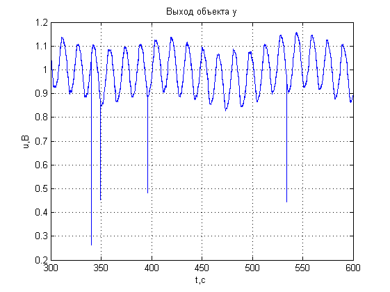
Fig. 5. The tuner operation
The plant output with the coefficients
is shown on the fig.6 The controller coefficients are .
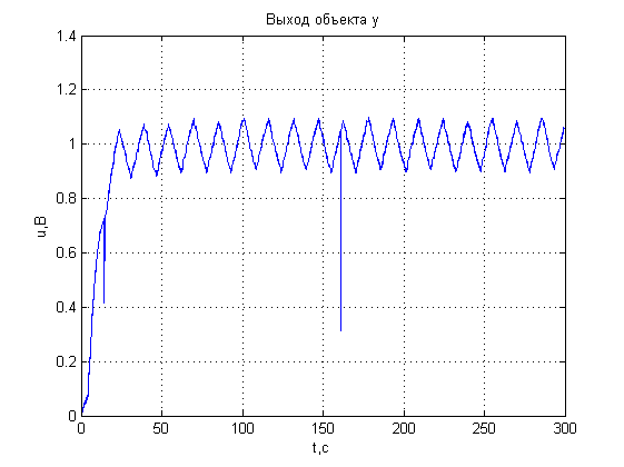
Fig. 6. The plant in the first regime. The controller is tuned by making use of the identified plant coefficient